Yagi Dimensions Are a Starting Point, Not the Final Antenna
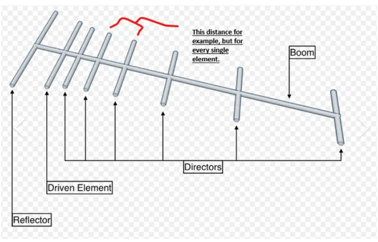
A Yagi antenna uses one driven element plus parasitic elements. The reflector is usually slightly longer than resonance, while directors are shorter. This creates a directional radiation pattern with stronger gain in the forward direction.
What the Calculator Estimates
This calculator estimates a practical first layout:
- Reflector: placed behind the driven element and made slightly longer.
- Driven element: the feed element, approximately half-wave before correction.
- Directors: placed in front of the driven element and made progressively shorter.
- Spacing: estimated as a fraction of wavelength.
Core Wavelength Formula
where λ is wavelength, c is the speed of light, and f is frequency. The calculator then applies length factors to estimate each element.
Why Wire Yagis Need Trimming
Wire antennas are affected by wire insulation, wire diameter, support ropes, nearby trees, the operator, coax routing, mast material, and height above ground. Because of this, the dimensions from a calculator should normally be built slightly long and trimmed during SWR or antenna-analyzer testing.
Common Mistakes
- Assuming a calculator produces final optimized dimensions.
- Forgetting to account for insulated wire velocity factor.
- Routing feedline close to elements without a choke or balun.
- Mounting the antenna too close to metal supports.
- Mixing meters, centimeters, feet, and inches during construction.
- Expecting the same dimensions to work perfectly in every environment.
Typical Element Roles
| Element | Typical role | Approximate length trend |
|---|---|---|
| Reflector | Reduces radiation behind the antenna. | Longest element. |
| Driven element | Connected to the feedline. | Near half-wave length. |
| Directors | Focus energy forward. | Shorter than the driven element. |
Frequently Asked Questions
Is this calculator enough to build a perfect Yagi?
No. It gives a useful starting design. For accurate gain, impedance, and pattern control, use antenna modeling software and final measurements.
Why is the reflector longer?
The reflector is made slightly longer so it behaves inductively and reflects energy toward the director side of the antenna.
Why are directors shorter?
Directors are shorter so they behave capacitively and help pull the radiation pattern forward.
Do I need a balun or choke?
Often yes. A choke or current balun can reduce feedline radiation and help keep the antenna pattern cleaner.
Can I use this for HF, VHF, and UHF?
The math scales with frequency, but construction details become very important. HF antennas are physically large, while UHF antennas are sensitive to small dimensional errors.